
Drawings that support a clear quotation
Drawing Preparation Guides
A clear drawing helps our engineers assess both the extrusion and its final assembly. Use these guides to identify critical dimensions, finishing allowances, visible faces and machining details. If drawings are unavailable, we can begin the review with a physical sample or a dimensioned sketch and clear photographs.
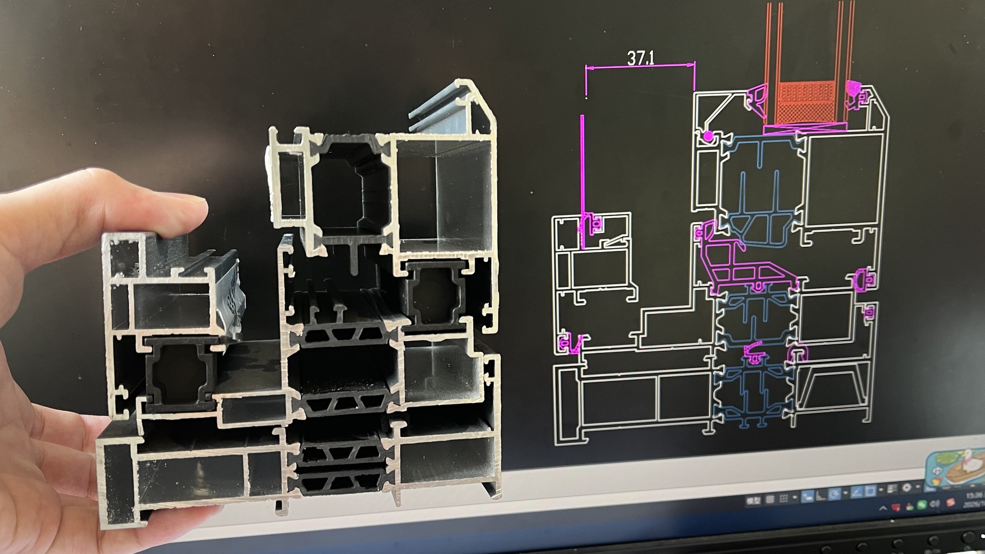
Show how the profile will fit and be used
Include the profile cross-section, application and mating components, not only the overall width and height. Mark critical grooves, sliding fits, wall thicknesses, visible faces and any special tolerances. For machined parts, add hole positions, reference datums and thread details. Explain whether cut ends and holes must be coated or may expose the underlying aluminum.
Critical fits and mating-part dimensions
A drawing may show a sliding channel or retaining slot without the required fit tolerance or mating-part dimensions. Without this information, our engineers cannot determine the intended clearance, increasing the risk of a loose or tight fit. Add a detailed assembly view or send the actual mating component for review.
Dimensions before or after finishing
State whether a close-fitting feature is measured in mill finish or after coating. Powder-coating thickness reduces the clear opening of a slot and can affect assembly. Identifying the inspection stage lets engineering assess the appropriate die allowance for the selected coating and mating component.
Visible decorative faces
Mark the faces that will be visible after installation, often called A-surfaces, with an arrow or dashed line on the cross-section. Their location affects extrusion weld-line placement, suspension points during finishing and visual inspection. Clear identification allows us to review appearance requirements before designing the die.
Machining datums and exposed cut surfaces
For punched, drilled or cut parts, identify hole-position datums and any cumulative spacing tolerance. Also state whether cut faces and hole interiors must be coated or may remain bare. These details help determine whether fabrication should take place before or after finishing and how the part will be inspected.
Accepted drawings and alternatives
We accept DWG, DXF and PDF drawings, plus STEP, STP and IGS models. Without a drawing, send a complete profile sample approximately 15–30 cm long or longer. Alternatively, provide a clear end-on photograph alongside a ruler, a dimensioned sketch and an explanation of the assembly. Mating hardware, gaskets or other component samples can help us check the intended fit.
Specify when critical dimensions must be met
State whether each critical dimension is inspected before or after surface finishing. Slots and mating features may need a coating allowance, assessed for the specific design, finish and mating component. Before die manufacture, Guantian issues a numbered and dated drawing for your written approval. Any subsequent change requires a revised drawing and renewed approval.
Start your project